Custom Draw Tubes: Types, Applications, and How to Choose the Right Design for CNC Lathes
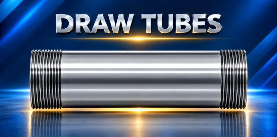
Custom draw tubes are important components in CNC lathes and other turning equipment that use drawbar-actuated workholding systems. They connect the machine’s actuation mechanism to a chuck or collet system, allowing the machine to open and close its workholding device.
Although draw tubes may appear to be simple cylindrical components, their dimensions, construction, and compatibility directly influence workholding performance, machine reliability, and production efficiency.
Manufacturers often require custom draw tubes when standard components cannot accommodate a particular machine configuration, workholding system, bar diameter, or production requirement.
Understanding the different types of custom draw tubes helps machine shops, engineers, and purchasing teams select equipment that supports their operations.
What Is a Custom Draw Tube?
A custom draw tube is a machine-specific tubular component designed to transmit axial force or movement between a lathe’s actuation system and its workholding mechanism.
In many CNC lathes, a hydraulic or pneumatic actuator moves the draw tube to operate a chuck or collet. The draw tube must accommodate the required stroke and force while maintaining proper alignment with the workholding assembly.
Unlike standard replacement components, custom draw tubes are engineered around specific machine dimensions and operating requirements.
Customization may involve the tube’s length, inside diameter (ID), outside diameter (OD), wall thickness, connection geometry, material, or mounting features.
A properly engineered draw tube must account for several factors:
- Machine make, model, and spindle configuration
- Chuck or collet system compatibility
- Required actuation stroke and force
- Available spindle bore and bar capacity
- Connection threads and mounting dimensions
- Material strength and operating conditions
- Clearance for other machine components
Because draw tubes are part of the workholding system, their design must be verified before installation.
What Are the Different Types of Custom Draw Tubes?
Custom draw tubes can be classified by their construction, dimensions, connection style, and intended application. These categories frequently overlap, meaning a single custom draw tube may incorporate several design features.
1. Standard-Configuration Replacement Draw Tubes
Traub TNA480 TNA500 TNA600 A8 Spindel Zugrohr Spannrohr 776921 10682628
cnc-markt.com
Replacement draw tubes are manufactured to match the functional requirements of an existing machine component.
These are commonly needed when an original draw tube becomes damaged, worn, or unavailable from the original equipment manufacturer.
A replacement may require custom manufacturing because of unusual dimensions, discontinued equipment, or modifications made to the machine.
Common applications include:
- Replacing damaged draw tubes
- Supporting older CNC lathes
- Restoring existing workholding systems
- Manufacturing replacements for modified machines
The replacement must match the machine’s actual requirements rather than relying on nominal dimensions alone.
2. Extended-Length Draw Tubes
Extended-length draw tubes are designed for applications requiring a different axial reach than the original configuration.
They may be necessary when a machine incorporates specialized workholding equipment, additional mounting components, or a modified actuator arrangement.
An extended draw tube must maintain adequate structural strength while transmitting the required actuation force.
Additional length can introduce engineering considerations involving deflection, alignment, and available machine clearances.
Typical applications include:
- Modified CNC turning equipment
- Specialized chuck configurations
- Custom workholding assemblies
- Machine retrofits requiring different connection locations
Increasing draw tube length does not automatically increase the machine’s usable bar capacity. The entire spindle and workholding configuration must be evaluated.
3. Large-Bore Draw Tubes
Large-bore draw tubes are designed with an increased internal diameter to accommodate larger bar stock or provide additional internal clearance.
In bar-fed CNC turning operations, the draw tube’s internal opening can influence the maximum bar diameter that passes through the workholding assembly.
However, increasing the internal diameter reduces available wall thickness unless the outside diameter can also change.
Engineers must balance internal clearance against strength, actuation loads, and the surrounding spindle geometry.
Common applications include:
- Bar-fed CNC turning operations
- Larger-diameter bar stock
- Specialized through-spindle workholding
- Applications requiring additional internal clearance
The draw tube cannot increase bar capacity beyond the physical limitations of the spindle, chuck, actuator, or other machine components.
4. Thin-Wall Custom Draw Tubes
Thin-wall draw tubes are engineered to maximize the available internal opening while fitting within a restricted outside diameter.
These designs can be useful when a machine has limited space between the draw tube and surrounding components.
Because wall thickness affects structural capacity, thin-wall designs require careful consideration of the material, axial loads, connection geometry, and operating conditions.
Typical applications include:
- CNC lathes with restricted spindle space
- Applications requiring additional bar clearance
- Specialized collet systems
- Machine configurations with limited radial clearance
A thinner wall is not inherently better. It must provide adequate strength for the intended workholding application.
5. Custom-Threaded Draw Tubes
Free Download: Machine Tool Drawbar, Steel (NAK55), Deep Small-Diameter Through-Hole Machining, Concentricity 0.01, Perpendicularity 0.01 – Glory Co., Ltd.
ja.nc-net.or.jp
Threaded draw tubes incorporate connection features designed for specific actuators, chucks, or collet mechanisms.
Thread geometry is particularly important because the connection must transmit the required forces without loosening, binding, or damaging adjacent components.
Customization may involve thread diameter, pitch, length, engagement, or connection location.
Common applications include:
- Specialized chuck installations
- Collet closer conversions
- Replacement of discontinued components
- Workholding system retrofits
- Custom actuator connections
Thread specifications must be verified against the mating components. Similar-looking threads are not necessarily interchangeable.
6. Multi-Piece Draw Tube Assemblies
Some applications may require draw tube assemblies manufactured from multiple connected components rather than one continuous tube.
A multi-piece design can accommodate particular assembly, installation, or maintenance constraints.
Depending on the machine, these assemblies may incorporate threaded connections, adapters, or other engineered joining features.
Potential applications include:
- Machines with restricted installation access
- Specialized workholding arrangements
- Equipment incorporating custom adapters
- Retrofitted actuation systems
Every connection must maintain the required strength, alignment, and resistance to loosening under operating conditions.
7. Application-Specific Draw Tubes
Application-specific draw tubes are engineered for machine configurations that cannot be adequately supported by conventional replacement designs.
These components may combine custom lengths, internal diameters, mounting features, and connection geometries.
Examples include machines using specialized collets, custom chucks, or nonstandard actuator arrangements.
Their design depends on the complete workholding system rather than a single dimensional requirement.
Comparing Different Custom Draw Tube Designs
The following table summarizes the primary differences between common draw tube configurations.
| Draw Tube Type | Primary Purpose | Key Design Consideration |
| Replacement | Restore existing functionality | Exact machine compatibility |
| Extended-length | Accommodate modified axial reach | Strength and alignment |
| Large-bore | Increase internal clearance | Wall thickness and load capacity |
| Thin-wall | Maximize opening in limited space | Structural integrity |
| Custom-threaded | Match specialized connections | Thread engagement and geometry |
| Multi-piece | Accommodate assembly constraints | Connection strength and alignment |
| Application-specific | Support unusual machine configurations | Complete system compatibility |
These designs are not mutually exclusive. For example, a custom replacement draw tube may also require thin-wall construction and specialized threads.
How Do Custom Draw Tubes Work With Spindle Liners?
Draw tubes and spindle liners perform different functions, but they may operate within the same CNC lathe assembly.
A draw tube transmits actuation force to the workholding mechanism. A spindle liner reduces excess clearance around bar stock inside the spindle or draw tube, helping support the bar during rotation.
When both components are present, their dimensions and operating requirements must be compatible.
A properly selected spindle liner can help control unwanted bar movement, while the draw tube must continue to perform its workholding function without interference.
Engineers should evaluate internal clearance, liner mounting, bar diameter, spindle speed, and workholding movement together.
Not every draw tube requires a spindle liner, and not every spindle liner is installed inside a draw tube. The arrangement depends on the machine.
How Do You Choose the Right Custom Draw Tube?
Choosing a custom draw tube begins with understanding the machine and its workholding requirements.
1. Identify the Machine Configuration
Record the CNC lathe manufacturer, model, spindle configuration, and current workholding equipment.
Machines from the same manufacturer may use different draw tube designs depending on their spindle and actuator options.
2. Determine the Required Dimensions
Measure or verify the existing draw tube’s length, ID, OD, wall thickness, and connection geometry.
Where available, use original engineering drawings and machine documentation to establish the required dimensions.
3. Verify Workholding Compatibility
Identify the chuck or collet system, actuator type, required stroke, and operating forces.
These requirements determine whether a proposed draw tube can perform its intended function safely.
4. Evaluate Bar Stock Requirements
For through-spindle applications, identify the bar diameter, length, material, and feeding arrangement.
Confirm that the draw tube provides adequate clearance without compromising the workholding system.
5. Review Operating Conditions
Consider spindle speed, production frequency, coolant exposure, maintenance requirements, and any unusual loading conditions.
The selected design should accommodate the actual operating environment.
What Are the Benefits of Custom Draw Tubes?
Custom draw tubes provide value when a standard component cannot meet the machine’s functional requirements.
A correctly engineered component may offer several operational advantages.
Improved machine compatibility: Custom dimensions and connections allow the draw tube to interface with the intended actuator and workholding system.
Support for machine modifications: Custom manufacturing can accommodate equipment retrofits or specialized workholding arrangements.
Restoration of existing equipment: Replacement draw tubes can help return machines to service when original components are unavailable.
Better use of available space: Large-bore or thin-wall configurations may improve internal clearance where the machine’s structural limitations permit.
Reduced risk of fit-related problems: Accurate dimensions and verified connections help prevent interference, binding, and improper actuation.
These benefits depend on the quality of the engineering, manufacturing, and installation process.
What Can Go Wrong With an Incorrect Draw Tube?
An improperly specified draw tube can create problems extending beyond the component itself.
Incorrect length or connection geometry may prevent the chuck or collet from achieving the intended clamping position.
Inadequate strength or poor thread engagement can create additional risks under actuation loads.
Misalignment or interference may also affect machine operation.
Potential consequences include unreliable workholding, component damage, unexpected downtime, and serious operator safety hazards.
For these reasons, custom draw tubes should be reviewed against the machine manufacturer’s requirements and the complete workholding system. Installation and functional testing should follow applicable machine and workholding safety procedures.
Why Work With an Experienced Custom Draw Tube Manufacturer?
Custom draw tubes require more than basic tube machining. Their design involves dimensional compatibility, material selection, connection geometry, and an understanding of CNC workholding systems.
Manufacturers such as JF Berns bring machine-specific engineering and manufacturing experience to custom lathe component applications.
JF Berns works with manufacturers on CNC lathe accessories and custom equipment requirements, including spindle liners, bar-support solutions, and related machine components.
For a custom draw tube inquiry, the most productive starting point is a review of the machine specifications, existing component, workholding arrangement, and required modifications.
This helps determine whether a replacement design or a more specialized solution is appropriate.
Frequently Asked Questions About Custom Draw Tubes
What is the difference between a draw tube and a drawbar?
Both components transmit force or movement to a workholding mechanism. A draw tube generally has a hollow construction, which may allow bar stock to pass through it, while a drawbar may be solid or configured differently. Terminology varies by machine manufacturer.
Can a custom draw tube increase CNC lathe bar capacity?
Potentially, if the existing draw tube is the limiting component and sufficient space and strength are available. The spindle bore, chuck, actuator, and other machine components may still restrict the maximum bar diameter.
Are all CNC lathe draw tubes interchangeable?
No. Draw tubes must match the machine’s actuator, workholding mechanism, dimensions, and connection requirements. Even machines with similar spindle sizes may require different designs.
What materials are used to manufacture custom draw tubes?
Steel is commonly used because of its strength and machinability. The specific grade, heat treatment, and surface finish depend on the application and engineering requirements.
Can a damaged draw tube be replaced with a custom component?
Yes, provided the replacement can be engineered to meet the machine’s dimensional and functional requirements. An existing part, technical drawing, or verified machine specifications can help establish the design.
What information is needed to request a custom draw tube?
Manufacturers should provide the machine make and model, workholding system, actuator details, existing draw tube dimensions, connection specifications, bar stock requirements, and any available technical drawings.
Finding the Right Custom Draw Tube for Your Operation
Custom draw tubes play an important role in CNC lathe workholding, particularly when standard components cannot accommodate the machine’s dimensions or operating requirements.
Replacement, extended-length, large-bore, thin-wall, threaded, and multi-piece configurations each address different engineering challenges.
The correct design depends on the machine, actuator, workholding mechanism, available space, and production requirements.
For manufacturers evaluating a replacement or custom configuration, JF Berns can be contacted to discuss the application and determine the appropriate next steps for technical review. Providing machine specifications, component drawings, and workholding details will help establish the requirements for a qualified inquiry.